Amine
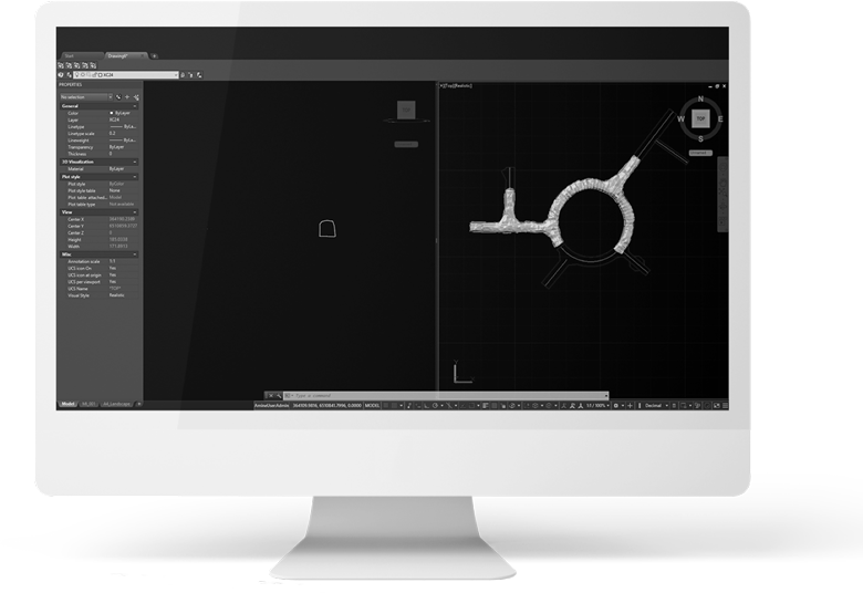
The most advanced AutoCAD-based mine design software – Amine is the perfect tool for all underground mine surveyors. It includes a comprehensive suite of tools including a laser offset function, automated CMS slicing and underground monthly reporting summary which simplifies and streamlines daily survey tasks.

Easy To Use
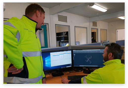
Amine is an advanced AutoCAD-based mine design software that is the perfect every day accompaniment for all underground surveyors. It provides dedicated survey tools, processes and workflows to efficiently process survey data from survey instruments, report on end of period measurements and create survey memos.
Flexible & Secure
With the ability to deliver effective and accurate survey mine plans through an easy to use powerful 3D graphics engine, it also alleviates tedious manual labour by providing automated workflows that can be aligned to your company’s specific need – completely customisable to every individual. Amine addresses the need of on-site survey staff, consultants and contractors whilst being flexible enough to be used for any commodity, orebody and underground mining method.

Benefits
A comprehensive suite of tools specially dedicated to underground surveyors.
Increased team efficiency with seamless data sharing between departments.
Automate tedious tasks and achieve results quicker than you ever thought possible.
Automatic processing of survey data through intelligent CAD tools.
It is based on the easy to use, universally accepted and widely used graphical engine, AutoCAD.
GIS style interface means you just need to select the data required and the system will automatically find the information for you.
Dynamic and easy to use plotting reduces the time taken to produce plans.
Multilingual support: English, French, Spanish and Russian.
Functionality Highlights
File Manager
The Manager module is designed to:
- Organise and manage drawing files.
- Provide security and set user right to drawing files.
- Lock drawing files to prevent accidental overwriting.
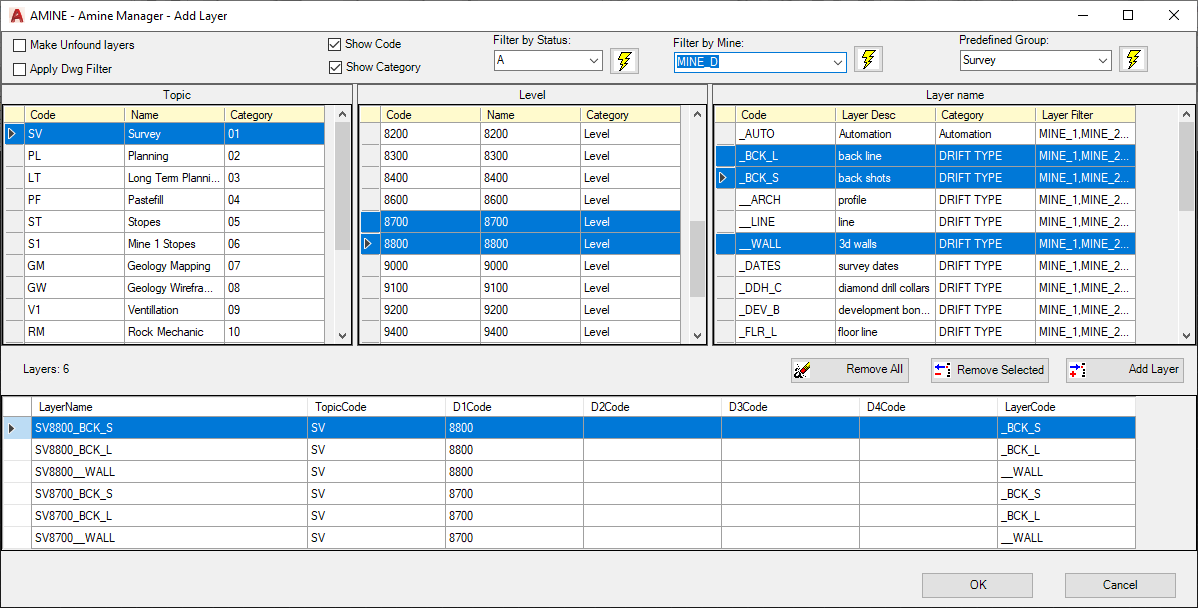
Manager offers a useful way of managing different types of information in a drawing through the Layer concept. Each layer is named according to a systematic convention and saved as a separate drawing file in a designated directory on the network using the Amine Manager.
The Amine drawing Manager enforces each Amine (AutoCAD) layer to have a specific naming convention according to the type information contained in the layer. For example: SV8700_1_WALL
- SV represents Survey information.
- 8700 represents Level 8700 of the mine.
- _1 represents Sublevel 1.
- _WALL represents surveyed Wall line.
Once a drawing has been assembled with all the desired layers, it can be saved as an AutoCAD drawing for subsequent use and for sharing it with other people. When a drawing is saved, the Amine Manager will save each layer to its appropriate location on the network and takes care of all the security aspects. When a drawing is re-opened the next time, the Manager scans all the required layers to make check if any modifications were made and then loads the layers with the most up to date information.
Layout
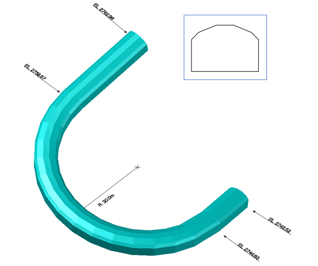
Layout helps you to design 3D structure: drift, ramp, and raise. Our interactive interface allows you to change design parameters quickly and effectively. The automatic annotation function makes the plan ready to print the moment the design is done.
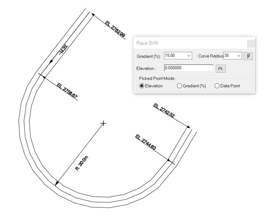
To create a solid drift, user simply select the profile, the solid of drift will be created. This solid drift can be used for drift compliance against the actual solid drift from survey. Annotation is created automatically. However, depending on your preferences, you can choose what information to display and how to display them.
Other features include:
- Cross cut interaction can be prepared with different radius at each side of the curve.
- Join 2 centerline running at different direction with different grade.
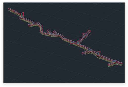
- Creating 3D structure in AutoCAD with both 3D mesh and 3D solid.
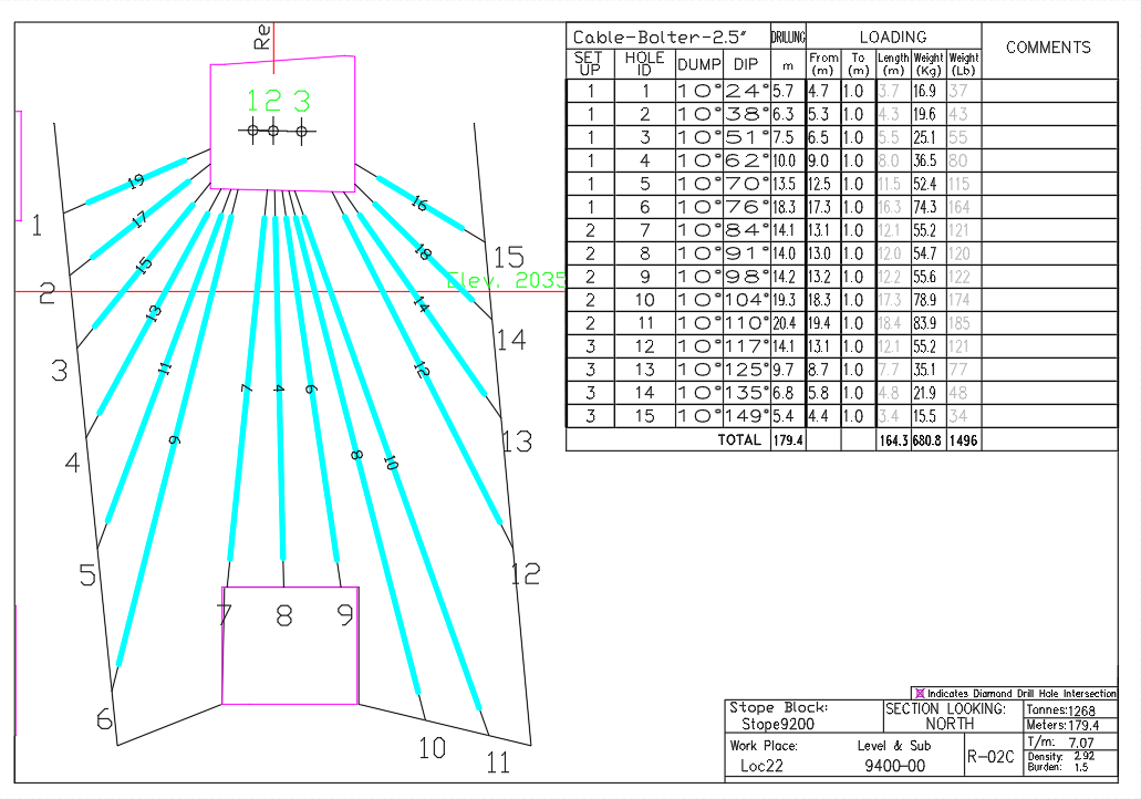
Drilling & Blasting
The Drilling and Blasting tools in AMINE are used to design stope drilling and blasting, including explosives loading and blast timing. This application assists blasting engineer(s) to create drill setups and layout blastholes.
Drilling
For drilling layout, this module offers 3 different methods: single, fan, and parallel.
Blasting
After the drilling design ready, user can specify the length for collar, charge and the powder length along the hole in the drawing area. The charge will then be displayed along the holes. Holes can be charged individually or all at the same time. After the holes are loaded with explosive, the user can then label them with the appropriate detonator number.
Data Import
The Data Import functionality allows you to download surveys from various types of total stations into the correct layers with all the correct line styles and attributes. Quickly import survey instrument data from multiple survey instruments and data sources. Automatically retrieve the corresponding layers to append the survey data to.
Solid Mesh Tool
Quickly generate solids from survey layers using the survey meshing tool. The simple user interface allows you to generate solids with ease and with very little input from the user.
Survey Memo Generation
The dedicated Survey Memo tool dramatically reduces the time taken to produce a ready to go Survey Memo. The user has the ability to produce a Survey Memo in as little as 60 seconds. This tool also reduces the risk of human input error by automatically populating the title block, as well as automatically attaching the corresponding ground support to the memo ready for plotting. This can be used with completely customisable title blocks and templates.
SDM
SDM is a module that tracks and reports on stope dilution. This is accomplished by comparing the cavity created during stope extraction with the planned stope that is designed by the drill/blast group as well as the optimised stope shape that is designed by the planning engineer. The process involves the conversion of various components into a valid AutoCAD solid so that they may be used in Boolean operations. The automated meshing of CMS slices allows for quick and easy stope solid generation.
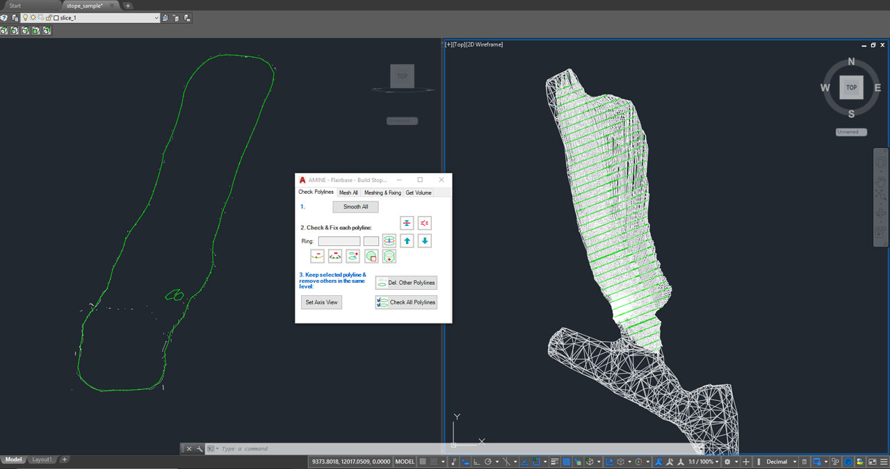
A simple interface allowing the user to step through each slice of the 3D mesh to create the solid. The user will be able to edit each line easily with minimal training.
EOM Reporting
The EOM reporting function removes a lot of the conventionally manual and tedious parts of the reporting process. This dramatically saves not only the user’s time but also their Manager’s time as well with the ability to report other attributes such as cost codes. The EOM function also automatically generates centre line advances of drives, volumes of each drive, EOM face positions.
Once all advancements have been generated for the month, the EOM function then compiles all advances for the month into a customisable report that can categorise the advance into appropriate areas such as operation development, capital development, horizontal development, verticle development. The user can also further catagorises by machine types such as jumbo, airleg, long hole etc.
As the monthly report is being created, plots of each heading are automatically generated with customised title blocks and the nominated scale. Once the user is happy with the presentation, the grid can be added and the monthly report is then completely ready to print.
Section
The SECTION module allows the user to define and cut sections through 3D objects throughout the mine at any location, orientation and at any inclined angle. Different ways of defining a section:
- Section in orthogonal view.
- Single section in any view.
- Multiple sections in any view.
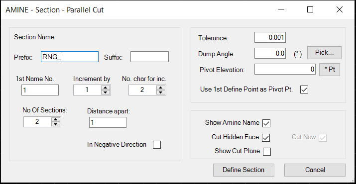
Other features include:
- Set dump angle to section.
- Show object names in sections.
- Unfold centerline, wall line, mesh and so on.
- Display DDh and entrance point in sections
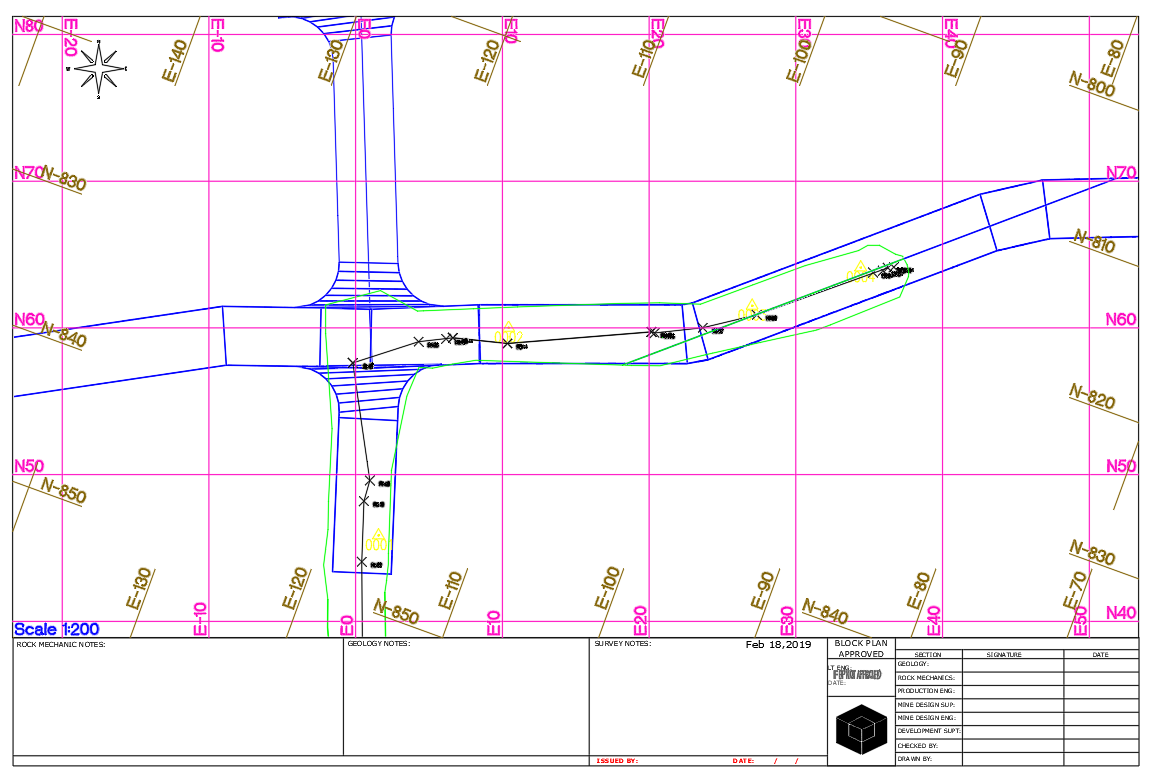
MineGrid
MineGrid allows you to create a grid and at the same time design a paper layout for plotting. To facilitate plotting, scale and printer are chosen by the user before placing the grid.
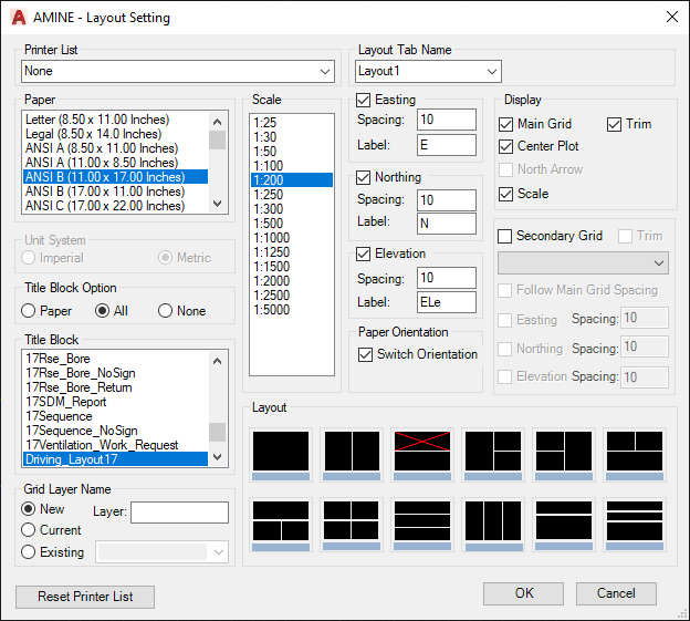
MineGrid allows you to display 2 grid systems; a World Coordinate System and a user defined Coordinate System, in a single viewport.
Functionality Highlights
File Manager
The Manager module is designed to:
- Organise and manage drawing files.
- Provide security and set user right to drawing files.
- Lock drawing files to prevent accidental overwriting.
Manager offers a useful way of managing different types of information in a drawing through the Layer concept. Each layer is named according to a systematic convention and saved as a separate drawing file in a designated directory on the network using the Amine Manager.
The Amine drawing Manager enforces each Amine (AutoCAD) layer to have a specific naming convention according to the type information contained in the layer. For example: SV8700_1_WALL
- SV represents Survey information.
- 8700 represents Level 8700 of the mine.
- _1 represents Sublevel 1.
- _WALL represents surveyed Wall line.
Once a drawing has been assembled with all the desired layers, it can be saved as an AutoCAD drawing for subsequent use and for sharing it with other people. When a drawing is saved, the Amine Manager will save each layer to its appropriate location on the network and takes care of all the security aspects. When a drawing is re-opened the next time, the Manager scans all the required layers to make check if any modifications were made and then loads the layers with the most up to date information.
Layout
Layout helps you to design 3D structure: drift, ramp, and raise. Our interactive interface allows you to change design parameters quickly and effectively. The automatic annotation function makes the plan ready to print the moment the design is done.
To create a solid drift, user simply select the profile, the solid of drift will be created. This solid drift can be used for drift compliance against the actual solid drift from survey. Annotation is created automatically. However, depending on your preferences, you can choose what information to display and how to display them.
Other features include:
- Cross cut interaction can be prepared with different radius at each side of the curve.
- Join 2 centerline running at different direction with different grade.
- Creating 3D structure in AutoCAD with both 3D mesh and 3D solid.
Drilling & Blasting
The Drilling and Blasting tools in AMINE are used to design stope drilling and blasting, including explosives loading and blast timing. This application assists blasting engineer(s) to create drill setups and layout blastholes.
Drilling
For drilling layout, this module offers 3 different methods: single, fan, and parallel.
Blasting
After the drilling design ready, user can specify the length for collar, charge and the powder length along the hole in the drawing area. The charge will then be displayed along the holes. Holes can be charged individually or all at the same time. After the holes are loaded with explosive, the user can then label them with the appropriate detonator number.
SDM
SDM is a module that tracks and reports on stope dilution. This is accomplished by comparing the cavity created during stope extraction with the planned stope that is designed by the drill/blast group as well as the optimised stope shape that is designed by the planning engineer. The process involves the conversion of various components into a valid AutoCAD solid so that they may be used in Boolean operations. The automated meshing of CMS slices allows for quick and easy stope solid generation.
A simple interface allowing the user to step through each slice of the 3D mesh to create the solid. The user will be able to edit each line easily with minimal training.
Section
The SECTION module allows the user to define and cut sections through 3D objects throughout the mine at any location, orientation and at any inclined angle. Different ways of defining a section:
- Section in orthogonal view.
- Single section in any view.
- Multiple sections in any view.
Other features include:
- Set dump angle to section.
- Show object names in sections.
- Unfold centerline, wall line, mesh and so on.
- Display DDh and entrance point in sections
MineGrid
MineGrid allows you to create a grid and at the same time design a paper layout for plotting. To facilitate plotting, scale and printer are chosen by the user before placing the grid.
MineGrid allows you to display 2 grid systems; a World Coordinate System and a user defined Coordinate System, in a single viewport.